- Shaker
- Reference accelerometer
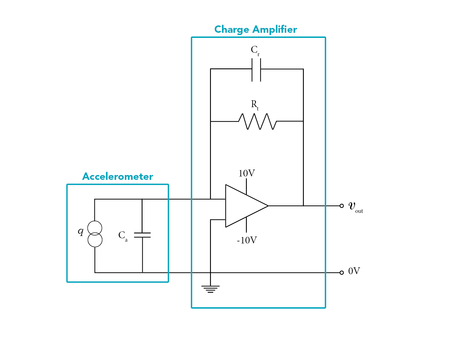
- Accelerometer circuit
The shaker circuit consists of a shaker, a function generator to create the desired waveform and in most cases an amplifier since the function generator will not have the power output required by the shaker.
Assuming the reference accelerometer is also a piezoelectric accelerometer, you would need to amplify and convert the charge signal to a voltage signal so the acceleration can be determined. This can be done by using a charge amplifier. A charge amplifier in its most basic form consists of a range capacitor, a time constant resistor, an operational amplifier and its power supplier. The range capacitor and the time constant resistor represent the cut-off frequency of the system. The gains are the ratio between internal crystal capacitance and the range capacitance.
The accelerometer for which the sensitivity needs to be determined should be placed on top of the reference accelerometer. Similar charge amplifier should be used. The voltage signal can be read in an oscilloscope. It is generally advised to measure the acceleration at different frequencies. If nothing is specified, 1 kHz can be used.
Since accelerometers work outside of its resonance, it is obvious that one should stay away from their resonances. It is generally advised to avoid the shaker's natural frequencies too.

 EN
EN